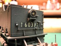
These are the marker lights we are going to “brighten up”. I have touched these with white paint so they are easier to see. I used a sharp pointed tool to dimple the centre of the ‘lense’ as a starting point for the drill. Do not use a power tool they are too ‘powerful’ and you do not have the same control as a pin vice. I used a 0.75mm drill to match the fibre optic that I had.
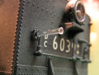
This is the test fit of the fibre in the hole. You all know how to ‘bell’ the end of the fibre as shown. (Secret – hold a soldering iron close to the end until you see it ‘bell’) When the fibre is pushed into place it will need to be trimmed so that only 5mm shows inside the body.
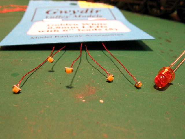
These are the Golden White LEDs that I used. They are 0.8mm Surface Mount LEDs with 5″ leads attached. Here they are shown against a normal 3mm Golden White LED. I bought these from Gwydir Valley Hobbies along with a packet of Surface Mount 1k resistors.
On the left is a 0.75mm drill (same size as fibre optic) and the SMD led being placed in the other end.
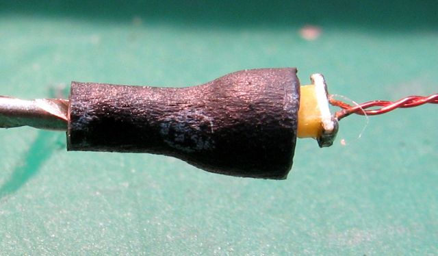
The Heat Shrink tube is then shrunk to hold the LED in place. The tube will then be pushed onto the fibre inside the body.
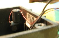
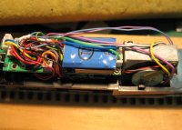
This shows the inside of the body with the tube over the fibre. Pass the cable behind the screw stub as shown here.
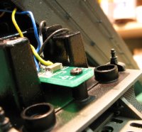
Here you can see the small circuit board for the headlight – just inside the body.
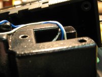
These are the wires for the headlight. This shows that the white wire was crimped between the two weights. check these then run your 4 wires along side these to the plug area.
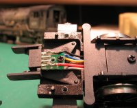
The plug area with the cover removed. You can see that there are 2 spare pins, these are the pins we will use for our markers. I nominated the pin next to the red wire as the ‘blue connection’. To this I soldered the long tail from one of the SMDs (the longer tail is the positive). I soldered the short tail from the other SMD to the other pin. Now the fun part, solder the other 2 wires to each end of the resistor and then fold a small piece of insulation around the resistor. It will fit under the shelf shown in the right of this photo.
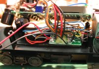
Under the main board in the boiler section there is a neat connection board. To this, I connected the red and black wires from the Function Decoder. The wires are shown coming from the bottom left. The Decoder I used was a TCS Fl decoder. This has 2 functions – one to drive each end. I prefer the TCS small decoders because their wires are very flexible whereas other brands are stiff.
I mounted the FL decoder above the board as shown – there is plenty of room. I ran the wires down to the connecter that goes to the tender and soldered to the 2 spare pins. I programmed the FL to operate the lights as directional, the same as the headlights. I also mapped them to work on Function One. This is normally used for the bell on American locos, but, Aussie locos do not have bells.
Here are the rear markers.
I did not try to ‘light’ the smoke illuminator at the front of the boiler.
If you fit a smoke generator then you will need to fit this — best of luck.
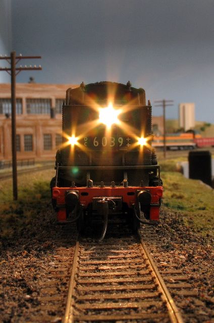
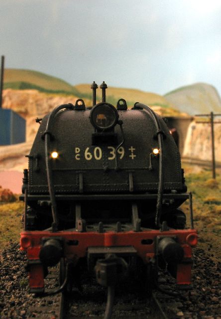
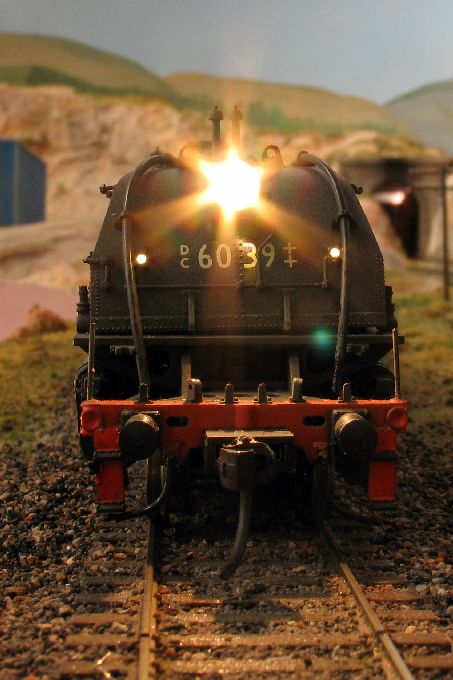
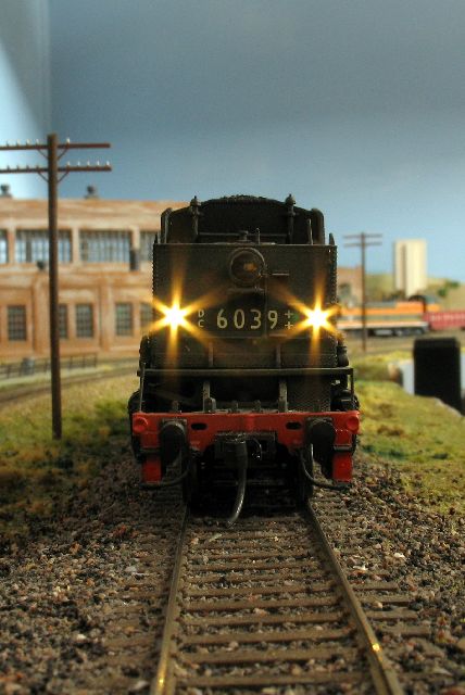
Now see the loco in action.
AD 60 Movie 1.5mg
I have an alternative method that uses the SMD led as the marker instead of using the fibre optic.