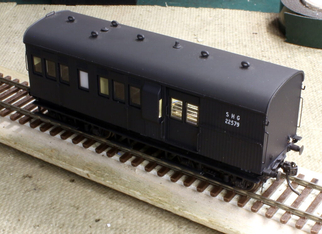
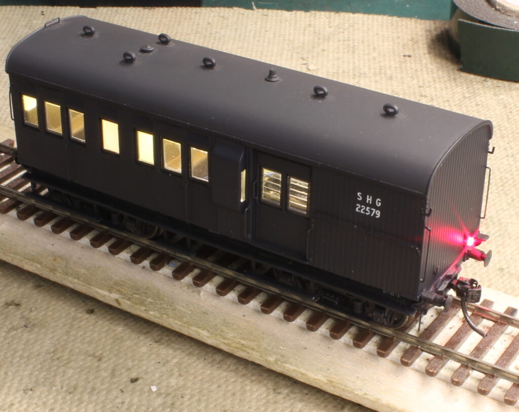
With advancement and availability of small parts suitable for model railways, some people like night running with lights on the locos and lights in rolling stock. Here is how I installed the interior lights – this one is an NSW SHG (Australian)- first with track power for the lights then updated with a Function Decoder for the lights (TCS FL4).
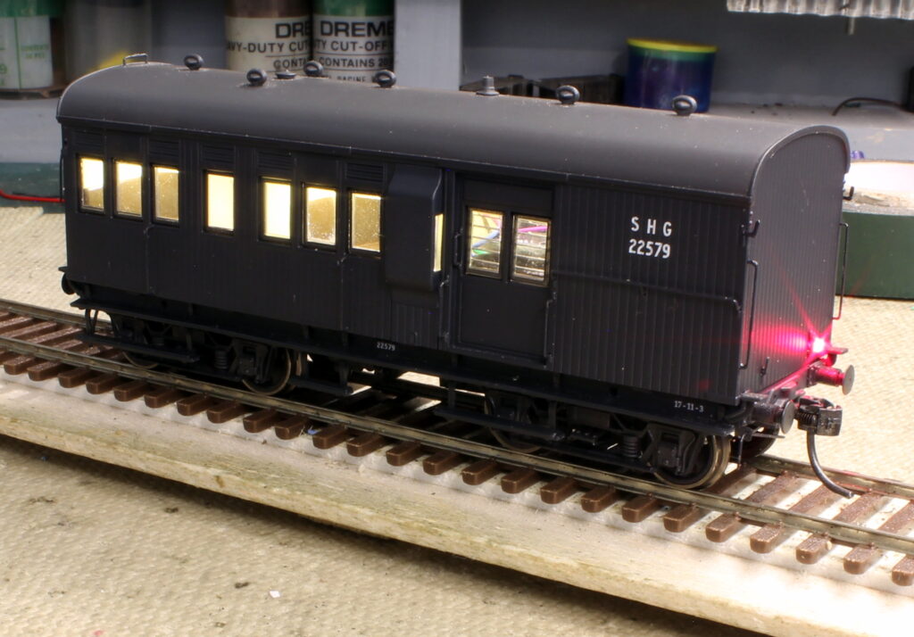
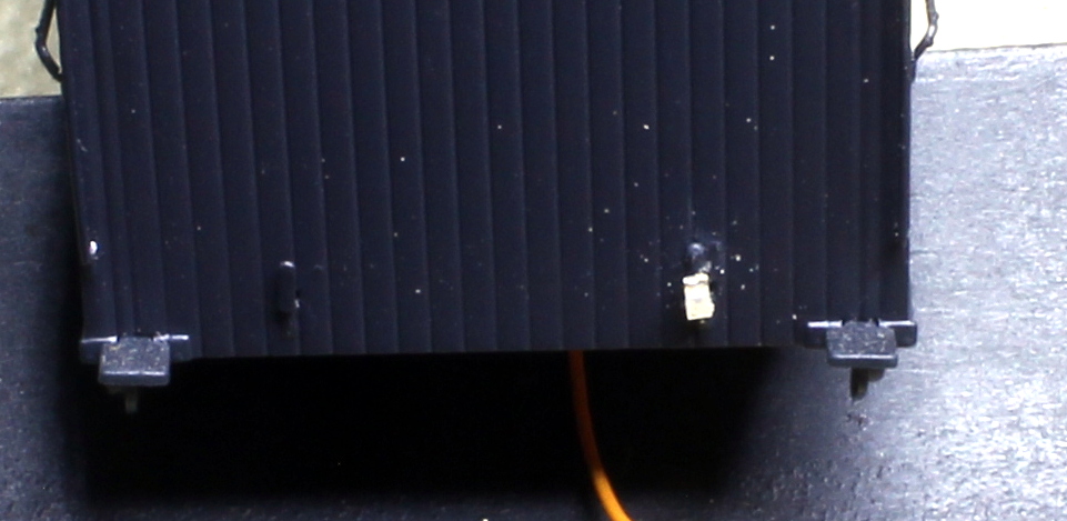
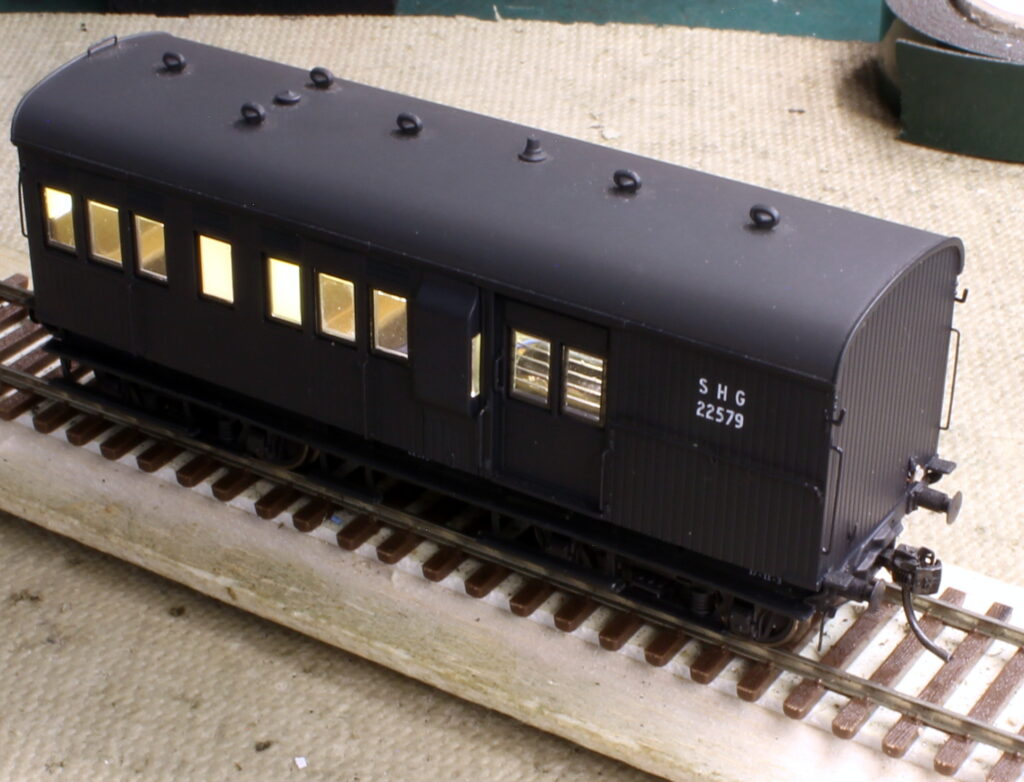
All the lights run straight off the track power, DCC of cause
The red LED looks a little too bright here – but each function output can be adjusted with a CV
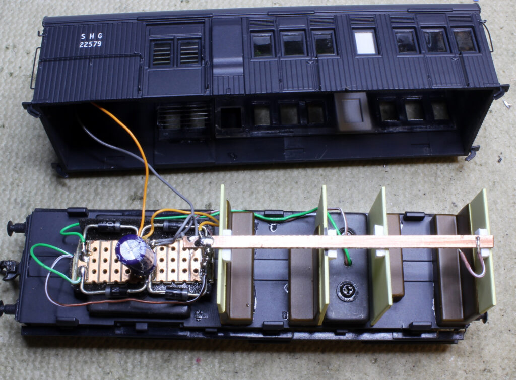
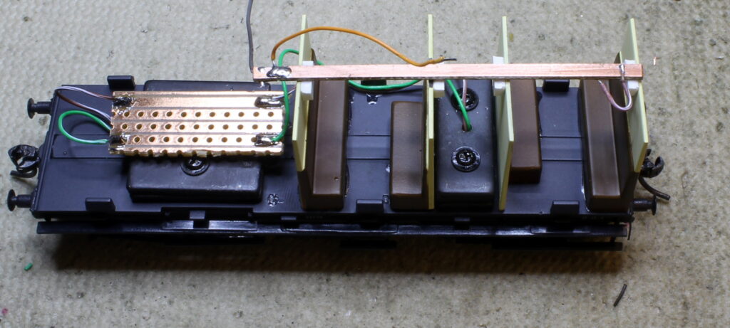
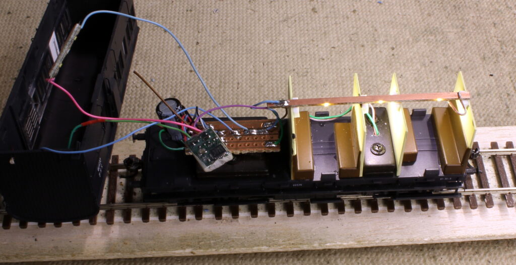
The lights in the passenger section are 3 x 603 SMD LEDs soldered in series with a 1K0 resistor – also SMD.
The Vero board on the left is used to mount and connect the diodes and capacitor and the wires from the power pickups.
Make sure you put the capacitor with the (-) to the negative side of the rectifier.
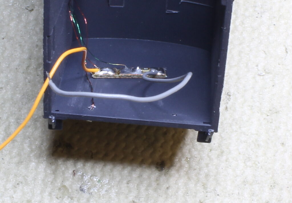

I use a short piece of PCB sleeper/tie glued to the top of the bolster on the truck.
A piece of 10 thou Phosphor Bronze is then soldered to the PCB – there is one on each side. They are bent at the ends to touch the back of the flanges – less drag.
Light wire (SWG 32 or SWG 36) is used to connect the pickups to the PCB in the car.
The board is mounted on double sided tape – make sure you only use the black stuff with the green backing. The white tape often has aluminium powder in it.
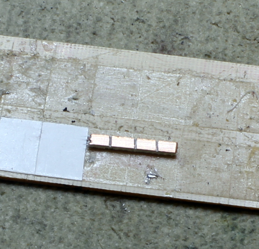
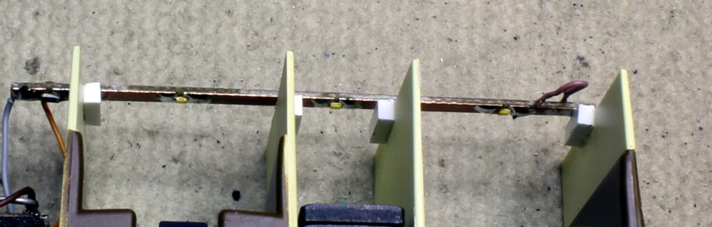
This is a short piece of PCB sleeper/tie.
I used a craft knife to cut through the copper – as shown. An SMD resistor is soldered across the middle break, and an LED across each of the other two gaps on either side – make sure both the LEDs are pointing the same way.
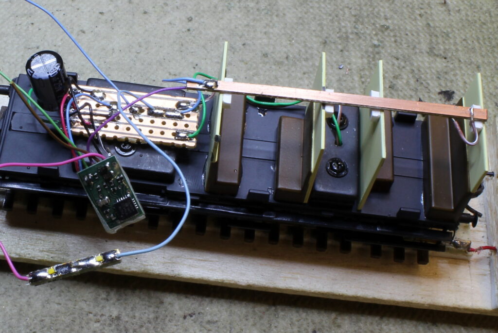
Here the decoder is attached to the PCB along with a suitable capacitor (24 volts 470uf).
The PCB on the bottom left is the light unit for the guard’s compartment and will be mounted on the roof.
The decoder here is a TCS FL4.
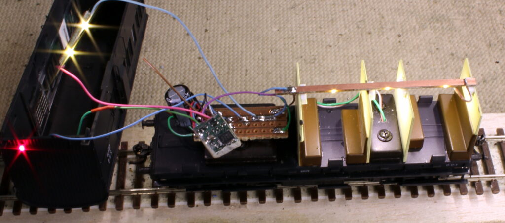
F1 switches on the RED rear light.
F3 controls the lights in the conductor’s section.
The brightness of each of the outputs from the decoder can be adjusted with CVs to get the right brightness.
This method can be applied to any car requiring lights.