Using Surface Mount Devices

LEDs have been around for over 40 years and some people are still afraid of them. LEDs come in many shapes and sizes and colours. The big advantage for us modellers is that they do not generate heat (no damage to the plastic shells) and are very forgiving of voltage variations. A 1.5 volt lamp will blow at 1.52 volts.

National Model Railroad Association | Using Surface Mount Devices

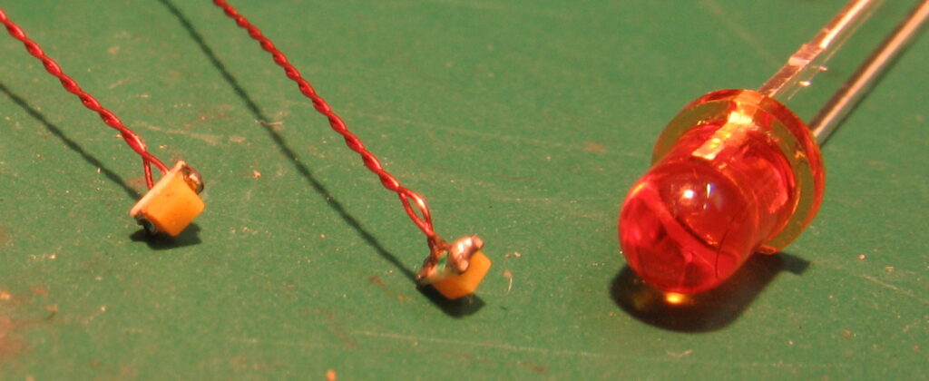
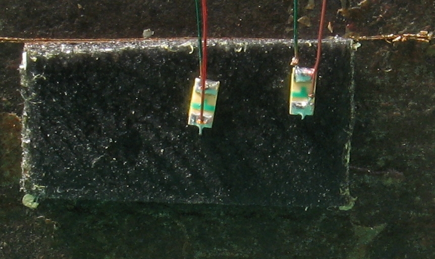
This photo shows the difference in size between a regular 3mm LED and a 603 surface mount. They are available in white, warm white, sunny white, golden white, red, green, orange which are suitable for our needs. There is also a bi-colour version (two colours) with common anode for use with decoders. All the surface mount units for model railroad use can be purchased with leads attached. The leads are 150mm long and the longer of the two leads indicates the Anode or positive end. This connects to the blue lead on a decoder.

National Model Railroad Association | Using Surface Mount Devices
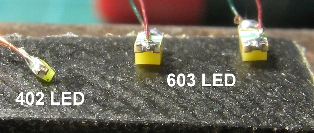
I am going to show you how to connect the leads to a SMD LED yourself. This saves the labour cost involved with units with leads attached. After doing the first 50 they become easy - trust me. The 603 is the easiest to use and easiest to obtain. Leave the 402 for a later date - maybe.
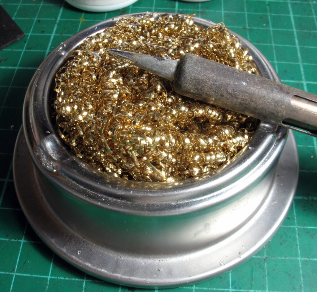
National Model Railroad Association | Using Surface Mount Devices

You will need a fine tip soldering iron – temp controlled to about 280 – 300C. Rosin core solder 60/40 and 0.71 mm diam. This is the solder you would use for all you normal model soldering.

A good iron cleaning station that looks like a Brillo pad – available form Dickie or JayCar. The most important other tool is Flux – not the thick paste you get from your friendly plumber but a good liquid type designed for modellers. I use Carrs Orange or Yellow for all electronic type work. Sources for Carrs (from the UK) are In Australia – and – In the USA

National Model Railroad Association | Using Surface Mount Devices

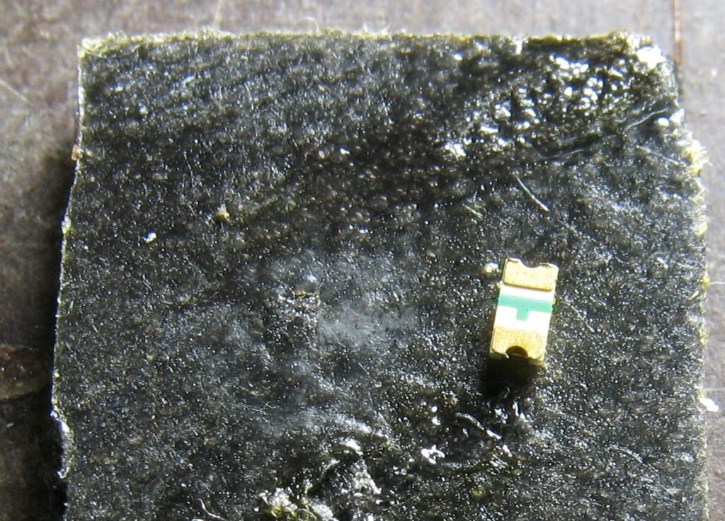
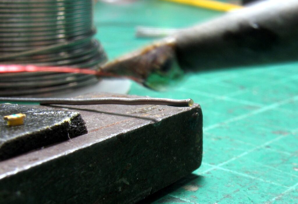
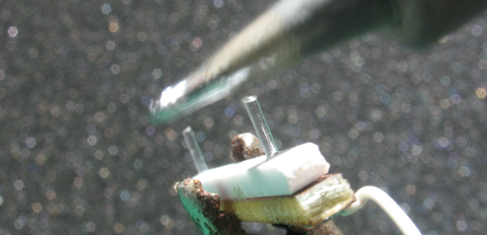
Step One Mount the LED on a small piece of double sided sticky tape. The tape needs to be on something firm – I use a steel 2″ square as shown.

Step Two We need to remove a short section of the enamel from the wire so that we have enough good tinned wire to solder to the LED.

National Model Railroad Association | Using Surface Mount Devices
To do this put a blob of solder on the iron and pass the wire through the solder for a few seconds.
National Model Railroad Association | Using Surface Mount Devices
You will see the shiny piece of tinned wire and you just need to trim to about 1mm in length.
National Model Railroad Association | Using Surface Mount Devices

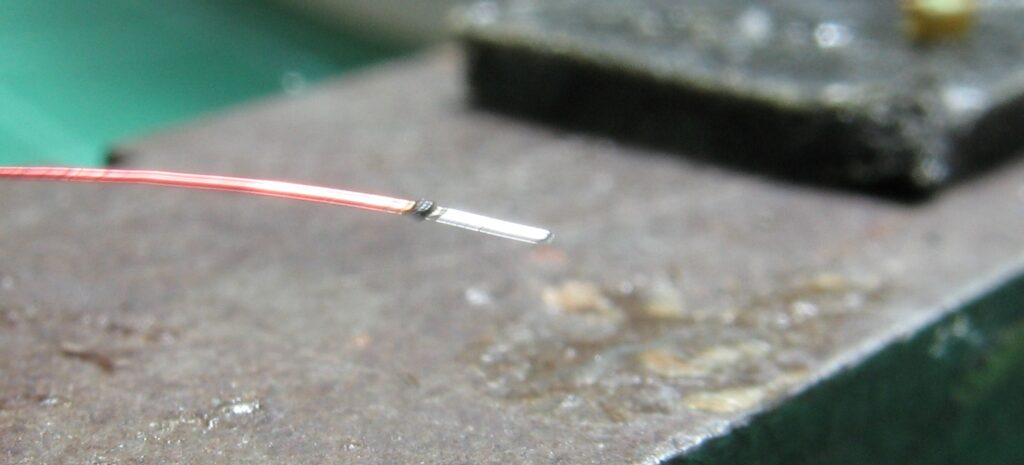
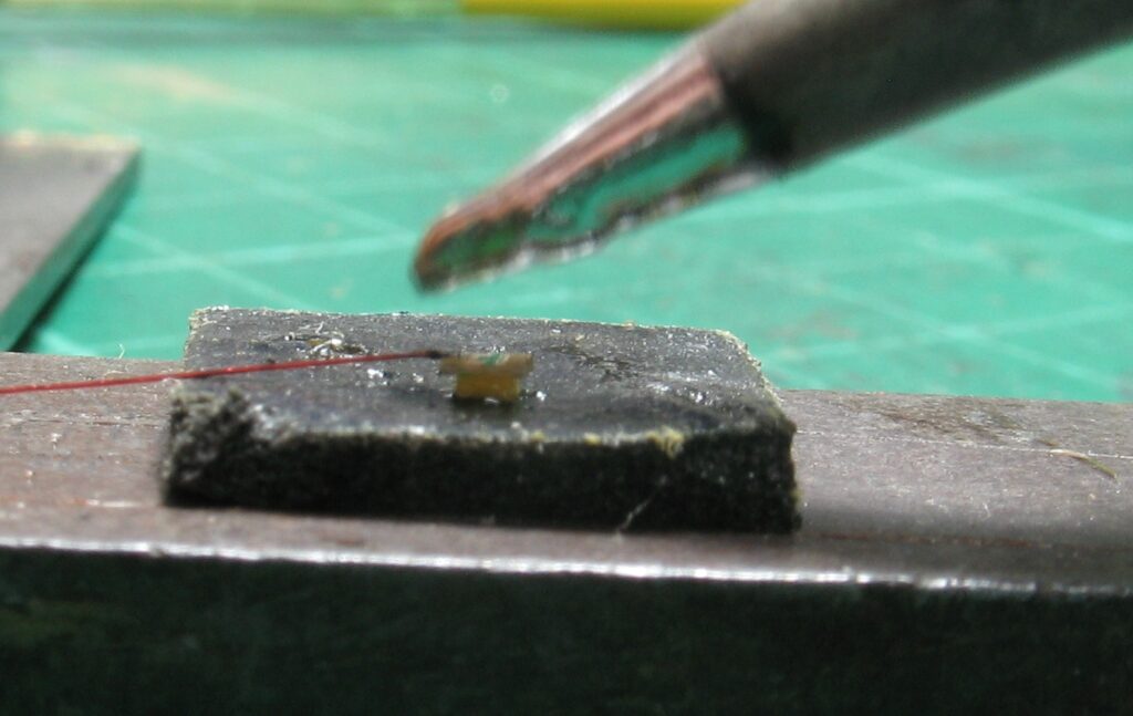
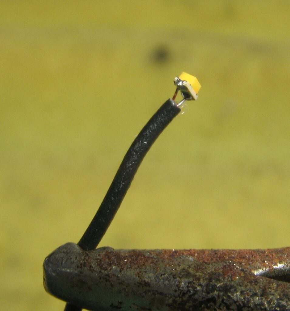
Step Three We now apply some flux to the back of the LED with a small brush. With this done we can now attach the first wire to the LED. Hold the wire on the gold section on the end of the LED and lightly touch with the iron. The flux will help to bond the wire to the pad instantly.

National Model Railroad Association | Using Surface Mount Devices
The wire I use is called “Magnet Wire” and is 0.004″ thick. My local source is Gwydir Valley Models
National Model Railroad Association | Using Surface Mount Devices
Do the same with the second wire and you are ready to test. This is style of connection is refferred to as “ditch light”, both leads go in the same direction.
National Model Railroad Association | Using Surface Mount Devices

I use a small battery powered unit – a “must have” tool is you are using any LEDs. You will need to tin the ends of the wire as you did for the other end. I normally use leads about 2″-3″ long. I am not sure where you would get one in the USA, but this site In the USA shows you the unit.

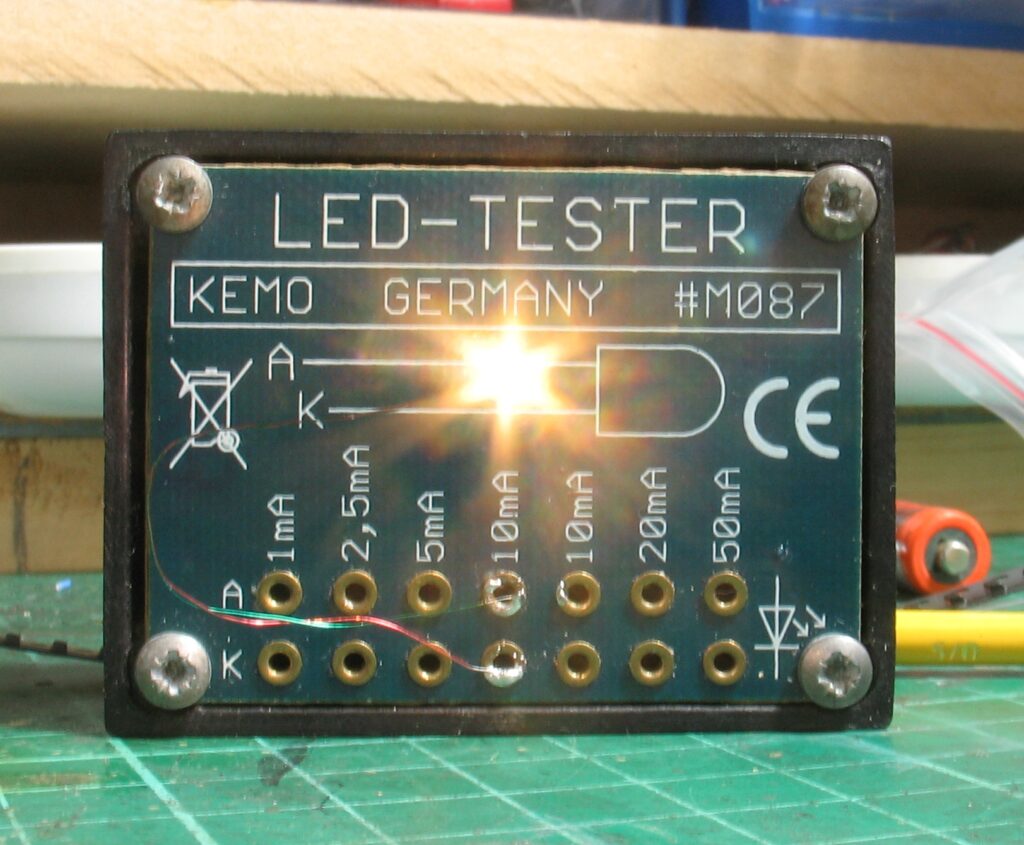
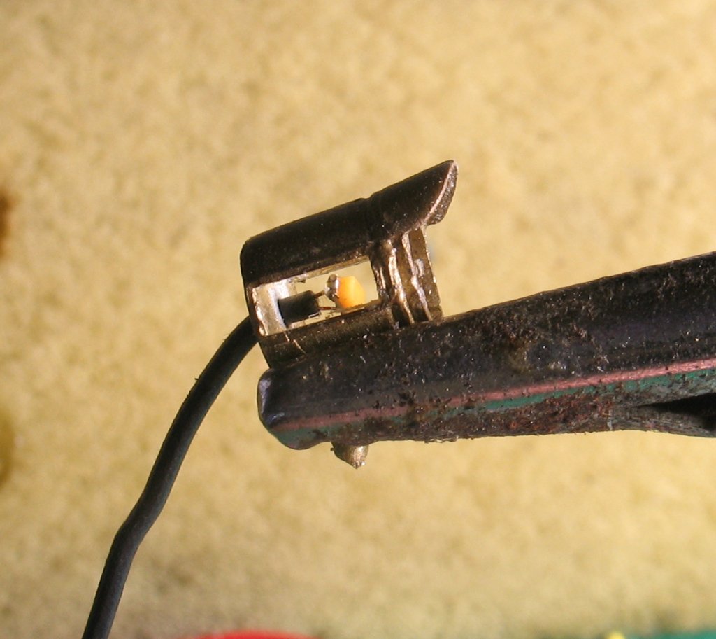
Here I have connected the LED to the 10 ma connection on the tester. Now to allay some of your fears. An LED will normally run on a 12 volt DC supply and require a resistor of 470 ohms to limit the current to 20 ma. Using a 1k0 resistor, (1000 ohms) will limit the current to 10 ma and I guarantee you will not see the difference when connected to your decoder. This will also mean that the LED is safe up to 24 volts and I only know one system that exceeds this level.

Where to use them

National Model Railroad Association | Using Surface Mount Devices

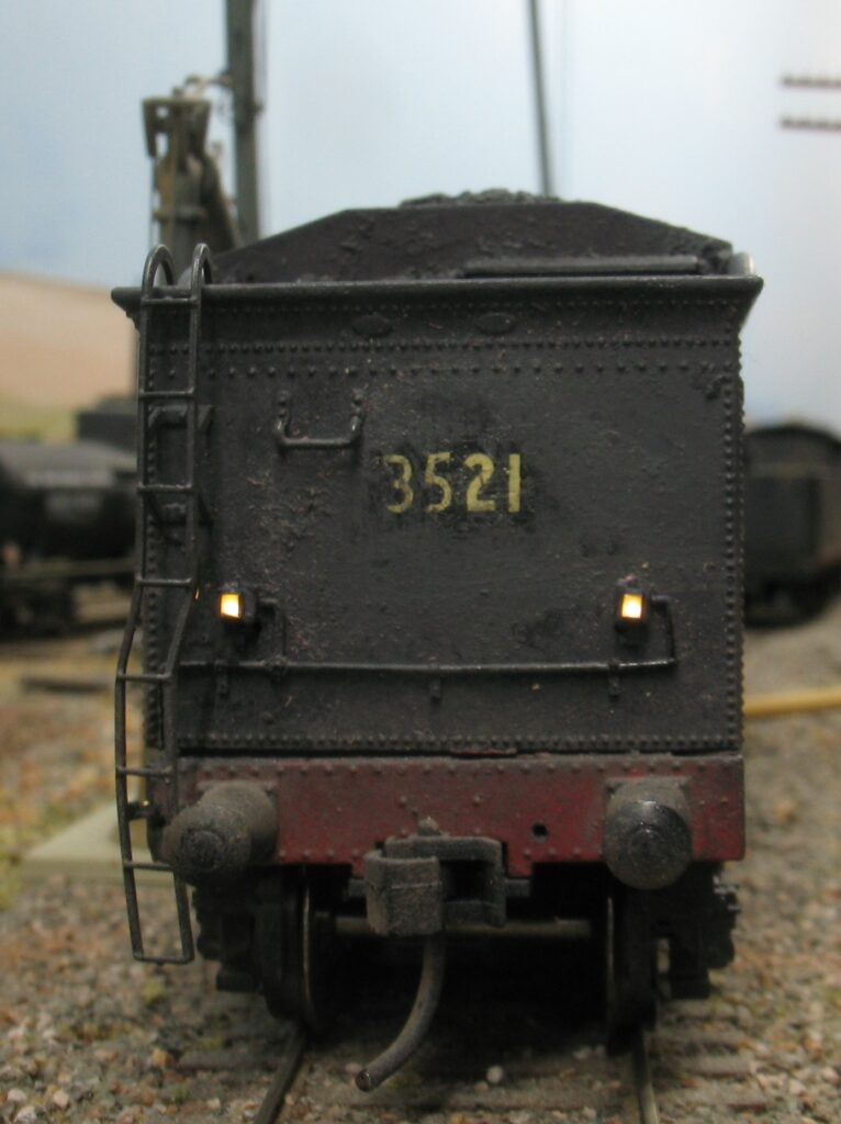
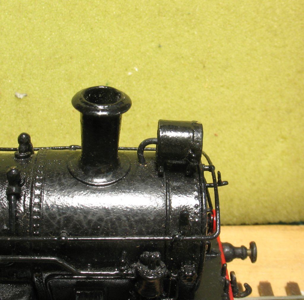
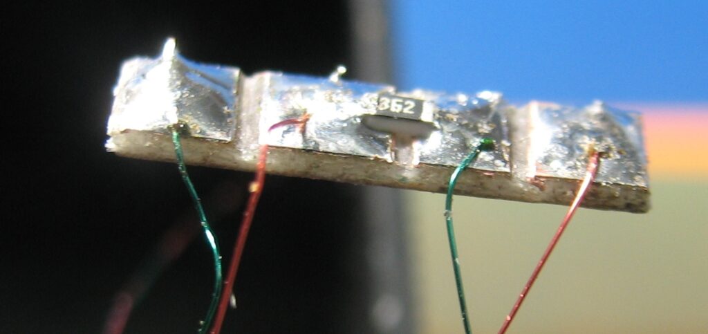
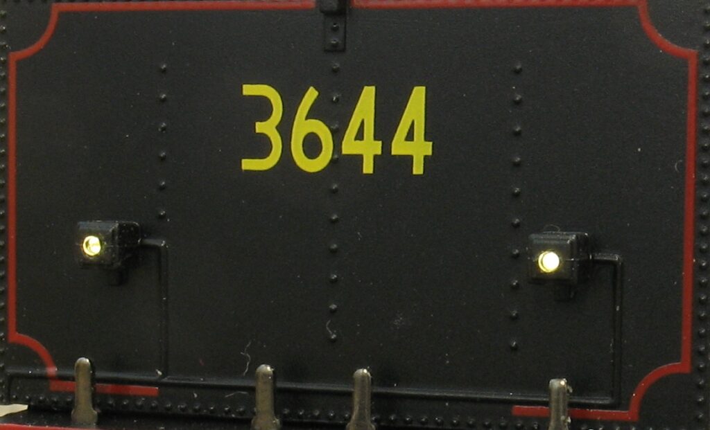
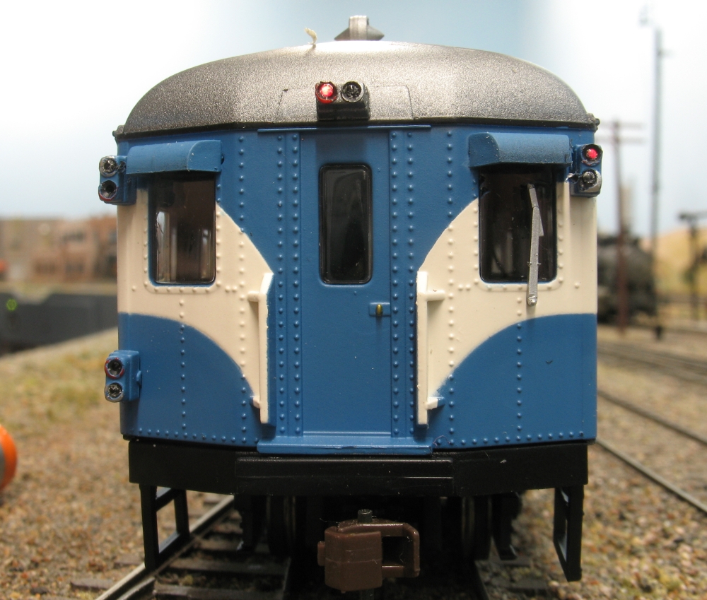
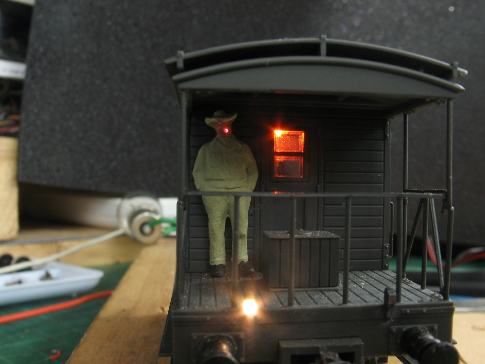
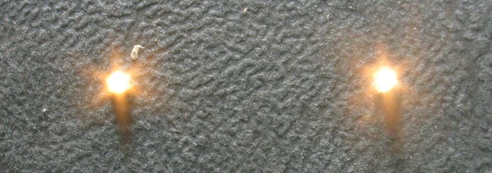
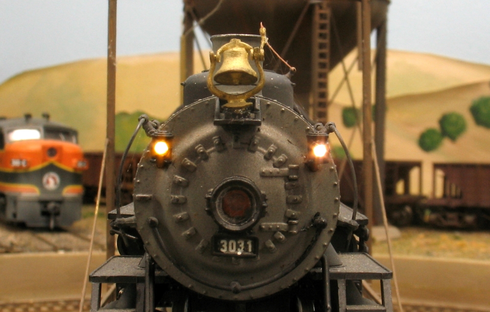
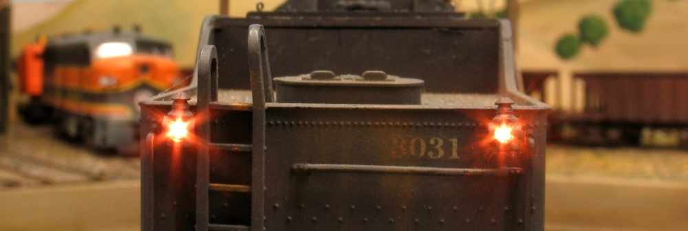
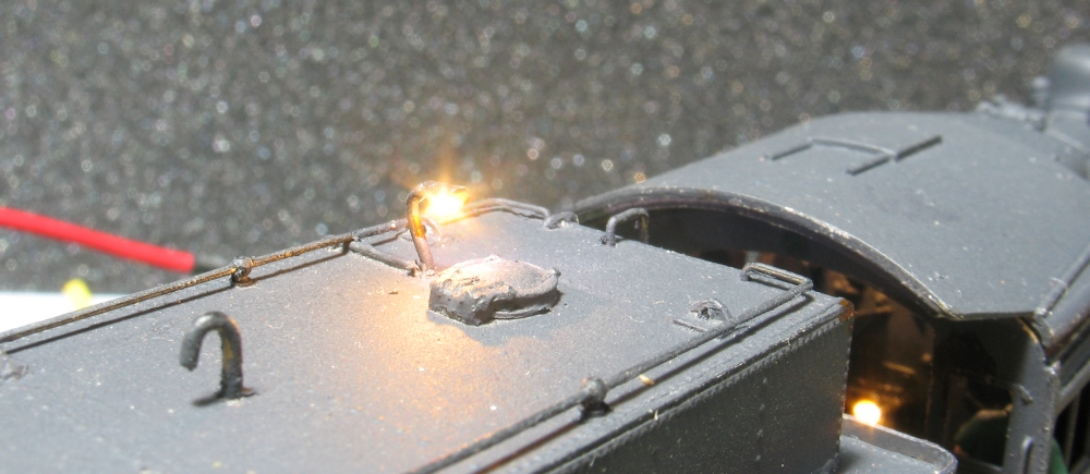
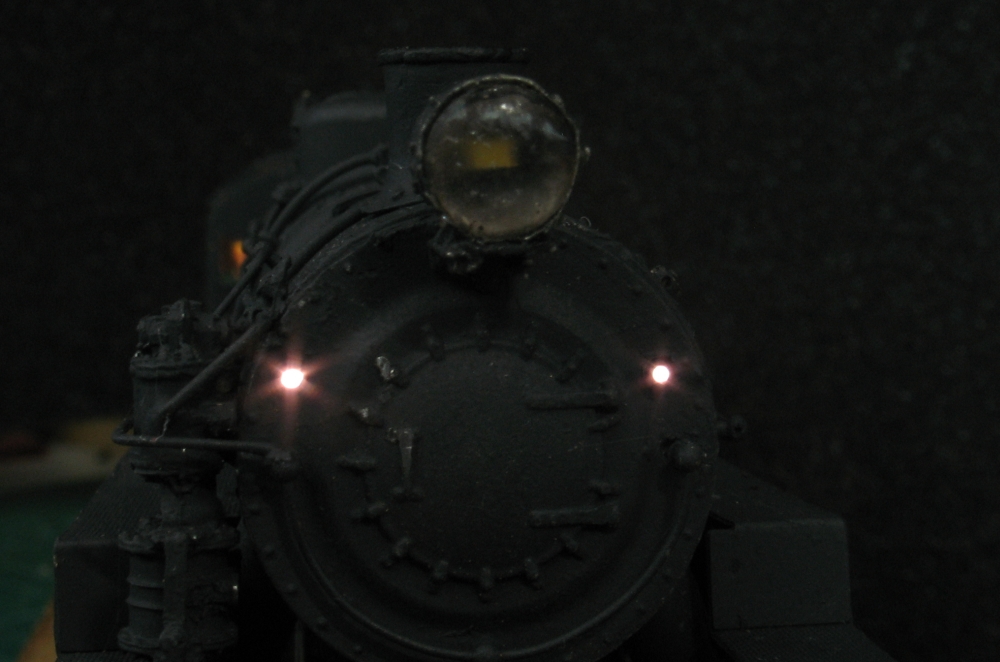
These two photos show them mounted as markers. Part of the cast on lamp housing has been removed and the SMD glued in place, and painted black. In these cases the 2 LEDs have been connected in series with a 3k6 resistor in between.

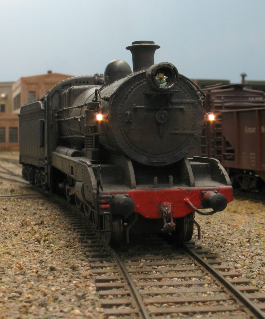
The loco is a NSW 35 Class from Austrains. It has QSI decoder for sound and a TCS FL4 for the lights.
Not shown here is the cab light.
The head light is also an SMD LED but that is factory fitted.

National Model Railroad Association | Using Surface Mount Devices
Here the 2 leads have been passed through a piece of cable sleeve left over from a decoder install.
National Model Railroad Association | Using Surface Mount Devices
Here the sleeve has been passed through the back of a brass headlight and glued in place with ACC.
National Model Railroad Association | Using Surface Mount Devices
The lead comes through the lamp and down into the boiler. It can go down through the lamp into the boiler, but in this case the holes were already there from an old lamp.
National Model Railroad Association | Using Surface Mount Devices

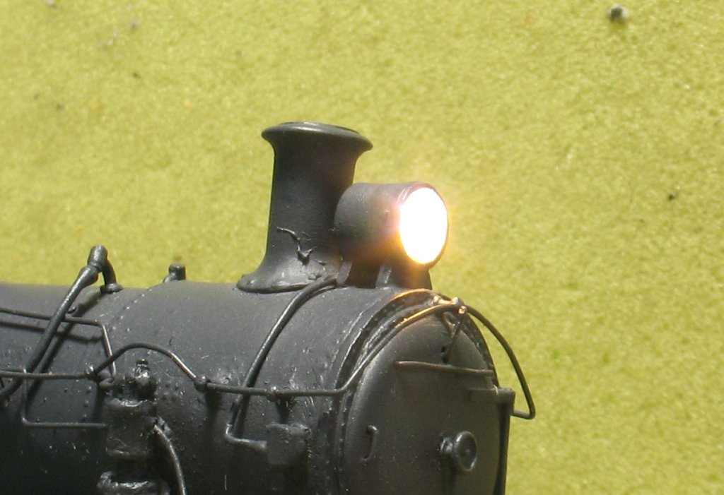
All finished and working. The head light is filled with Microscale “Crystal Clear” to seal the LED and prevent movement. The light here looks a little too bright for a steamer – that is just the photo, but if you wish to “tone down” the light then just add a coat of paint – normally Tamya’s Clear Orange.

The next part

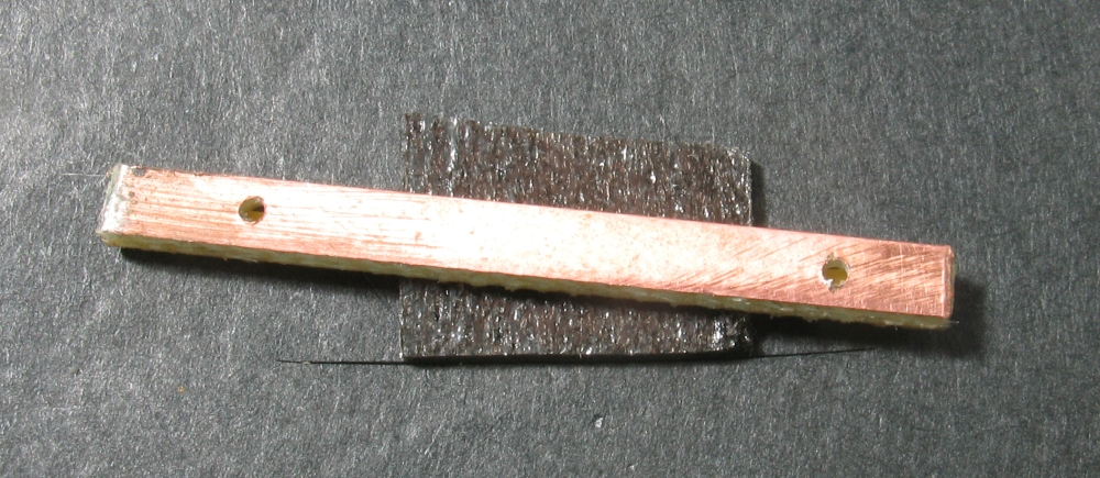
Next, is mounting these little babies on a small piece of circuit board such as a piece of Clover House Sleeper (tie) with a surface mount resistor.

National Model Railroad Association | Using Surface Mount Devices

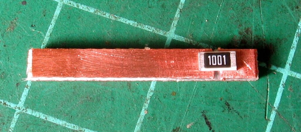
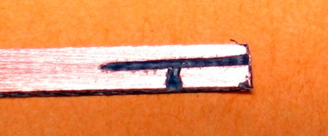
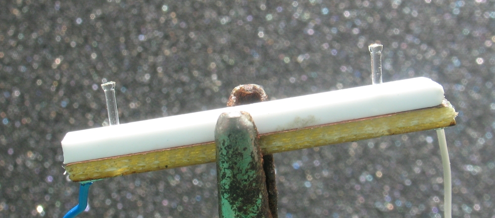
Step A involves wiping the piece of pcb with the flux brush. You will see the colour of the cladding change as the flux removes the oxidisation. Then file a small slot across the pcb.
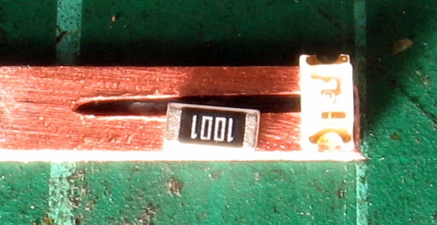
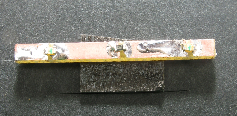
Step B The LED will sit across the slot as shown (this is actually a resistor). You then touch the pcb next to the LED and the solder will immediately run under the LED. Then do the other side of the LED.

National Model Railroad Association | Using Surface Mount Devices
We can also add an SMD resistor to the LED as shown. I have used slightly larger components for the photographs.
National Model Railroad Association | Using Surface Mount Devices
The first photo shows the slots cut, and the second shows the parts in place ready for soldering. We can also use the PCB for connecting our fine wires to a resistor and to the leads from the decoder.
National Model Railroad Association | Using Surface Mount Devices
This shows the leads from 2 marker lights connected in series with a resistor between them. The resistor shown is 3k6 (3600 ohms) and the LEDs are the rear markers on a NSW 36 class. The wires from the decoder are attached to the two outer pads.
National Model Railroad Association | Using Surface Mount Devices
This is what they look like when finished, not too bright but just bright enough.
National Model Railroad Association | Using Surface Mount Devices

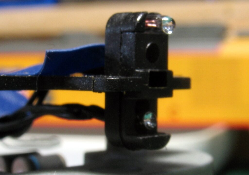
The next two photos show the Athearn Turbine lamp housing. The first is “as is” with 2 x 1.5 volt lamps they are not very bright and any voltage spike will blow them, if the resistor is changed to make them brighter then they could get too hot for the plastic body.

National Model Railroad Association | Using Surface Mount Devices
The second shows the replacement SMD LEDs. We now have a white mars light, a red mars light and dual headlights.
National Model Railroad Association | Using Surface Mount Devices
Although the SMDs can be very small, even the 402 is too big for some applications. This is when we can use relatively cheap fibre optics to get the effect we want. Such cases would be passenger cars, cabooses, and small marker lights on locos.
National Model Railroad Association | Using Surface Mount Devices
These 2 photos show the route indicator lights on a suburban electric car. This car has 4 x white lights and 4 x red lights and they are used in pairs to indicate the route.
National Model Railroad Association | Using Surface Mount Devices
This photo is pure whimsy. The white light is a 603 with leads glued to the light bracket. The one on the right hand side is red and these two change with direction of travel. There is a a light in the cab and Claude is smoking a cigarette. The cigarette is a fibre optic – through Claude and through the wall of the cab.

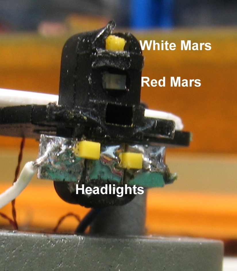
So, how to achieve these effects

National Model Railroad Association | Using Surface Mount Devices
This piece of PCB sleeper (tie) will fit inside the tender of a loco or it can be any length you like for other things. There are two hole drilled through the PCB – these are 0.75 mm (0.030″). the from the other side the hole is open out to just over 1.0 mm (0.040″) so that an LED can be soldered face down on the board.
National Model Railroad Association | Using Surface Mount Devices
This shows the components attached to the PCB. Notice that the 2 LEDs are facing the same way. The green marking denotes the Anode ( + ) and the Cathode ( – ). The anode is on the right. Also on the PCB is the resistor, this is marked 362 so has a value of 3k6 or 3600 ohms.
National Model Railroad Association | Using Surface Mount Devices
Here I have glued a piece of styrene to the PCB to represent the body of whatever we are fitting the lights to. This makes it easier to photograph. I have inserted 2 x pieces of 0.75mm fibre optic through the body and the PCB. There would normally be a light fitting on the body. Here I am “belling” the end of the fibre. I hold the soldering iron very close to the fibre for a few seconds and you can see the fibre belling out to look like a lens.
National Model Railroad Association | Using Surface Mount Devices
This shows the finished effect on the fibres. Adding the length of styrene is also suggested when mounting on a brass body as the brass is often too thin to work on.
National Model Railroad Association | Using Surface Mount Devices
This is the effect on the outside of the tender. I have also used this method on the Bachmann Tamper vehicle. The clear fibres are not really noticeable inside a cab and lets you get the light in the right place.

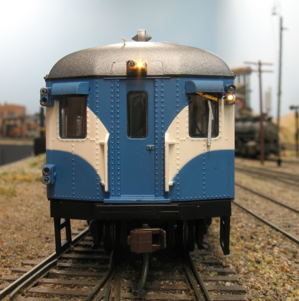
A few shots of things on my layout using fibre opticss and SMDs

National Model Railroad Association | Using Surface Mount Devices
A small workman’s shanty with a 402 LED in a Grandt Line shade. There is also a 603 inside the hut. The 2 wires pass through the shade and the through a short piece of cable sleeve from an old decoder.
National Model Railroad Association | Using Surface Mount Devices
The sun was still shining when they turned the lights on. These are 603 LEDs with Grandt Line shades. I had tried fibre optics on a similar station but were not bright enough to be seen on the layout.
National Model Railroad Association | Using Surface Mount Devices
Athearn Genesis 2-8-2 with 603 LEDs in the marker lights. The head light was drill out to take a 3mm LED long before 603s were available to us modellers.
National Model Railroad Association | Using Surface Mount Devices
Same loco from the rear but these are Fibre Optics.
National Model Railroad Association | Using Surface Mount Devices
A small inspection light above the oil filler hatch on a NSW 59 class. The lamp is a 402 LED with a small cover of styrene over the top to simulate the shade.
National Model Railroad Association | Using Surface Mount Devices
These are fibre optics at the front of the NSW 59 class. There is a bi colour 603 behind eash light fibre. A normal 603 is housed in the headlight case.

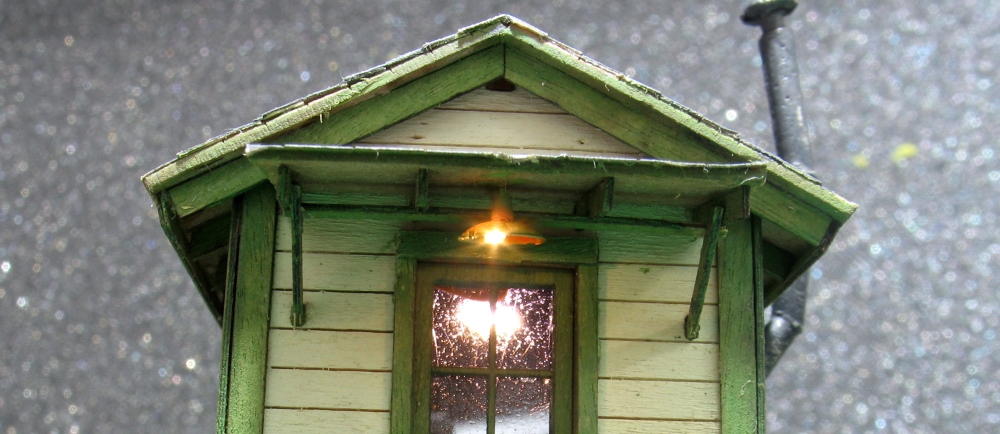
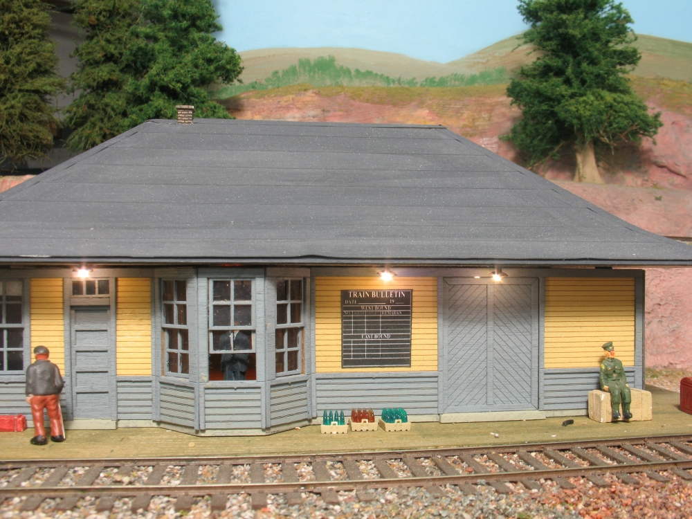
The possibilities are endless and the results satisfying

If you have fears of one side of the LED touching the shell of a brass of a loco, then use a 1k2 resistor on each side of the LED. If either side touches the shell there is a resistor between the shell and the decoder.

If you have an LED at the front of a loco or only have room to run a single wire, then connect the Anode ( + ) to one of the track pickup wires, or if it is a split frame then to one half of the frame instead of to the blue decoder wire. This will also drop the voltage to the LED by about 35%.