Adding sound and working marker lights
By Gerry Hopkins MMR
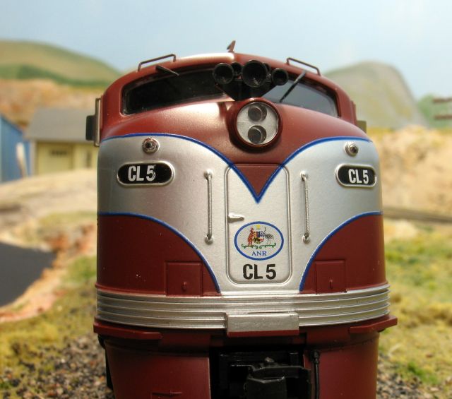
The CL/CLP is a great looking well detailed loco. It runs very smoothly and could pull a brick dunnie – even occupied. It is a very easy matter to fit a non-sound or sound decoder – even a plug & pray. When removing the body, first remove the handrail in front of the door on each side. Then, using toothpicks, ease the body away from the chassis. You can use many different non-sound decoders I used the TCS T1 with a short harness – because I had one. The Plug & Pray decoder would be the TCS DP5X. Remove the lighting board and plug the decoder in its place.
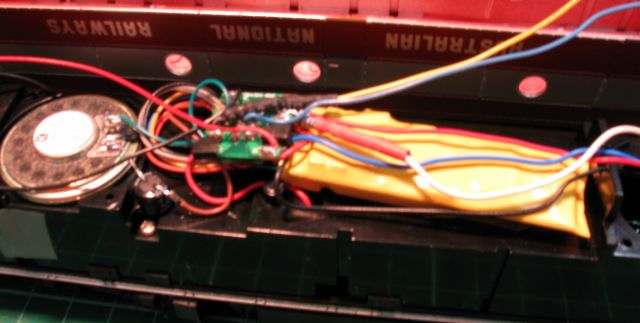
The sound decoder shown here is the new DSD101LC from Soundtrax (product number 820122). This is an EMD 2nd Generation sound chip – EMD 16-645E3/C, 3,300hp, (an SD40 for the yanks). Remove the existing light board and plug it in. Disconnect the white headlight lead and solder a 1k resistor in the lead.
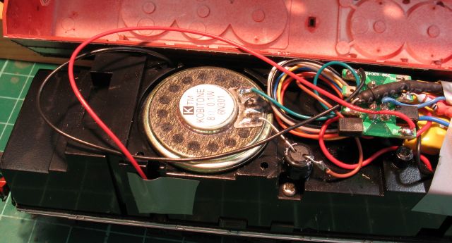
The speaker is a TDS (Tony’s Dream Speaker) 1.1″ 8-ohm unit. Run a small bead of glue around the edge of the hole and fix the speaker in place. I put the speaker over the rear of the two holes – one speaker is all you need. I turned the volume down to 60% and it is still loud. The 2 wires from the rear truck need to be rerouted through the holes in the side of the frame to allow the speaker to sit properly.
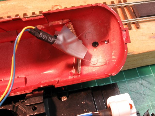
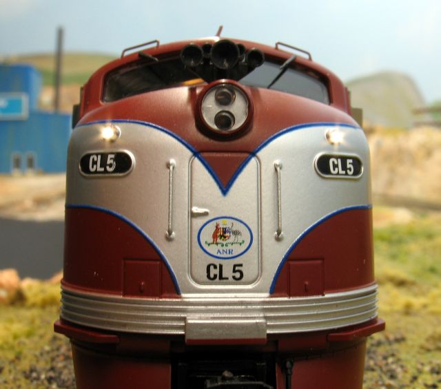
I first used a small pointed tool to dimple the centre of the marker light casting on the outside of the body. I then used a pin vice to drill a 10 thou hole as a lead through. I then drilled the hole out to 0.5mm for the 0.5mm fibre optic. I ran the blue(+) and yellow(-) leads from the decoder and soldered these to the Golden White 3mm LED. The longer lead on the LED is the (+). In one of these leads solder a 1k resistor. In the end of the LED I drilled 2 shallow holes for the 0.5 mm fibre, a little CA glue will hold them in place. Leave for 15 minutes for the CA to dry.
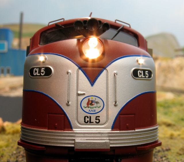
Then fit a piece of heat shrink over the LED as shown. I also added a small piece of tape to completely seal in the light. Cut the Fibres to about 1.5″ (18.65mm!) and pass through the body. Let the fibre show through for 0.25″ and bell the end. To bell the end, hold a soldering iron close to the end and you will see it form a bell shaped lense. Allow too cool for a few minutes then push the new lens back to the hole. Add a little CA glue to the inside of the body to hold it in place. Set the loco on the track and check that the lights work. If the decoder is new then the address is ‘3’. In forward the headlight will come on and the marker lights will come on in reverse – don’t worry we will reprogram this later.
Place a little bit of tape over the decoder to hold it in place and re-fit the body. We are now set to program the loco. On the program track, set the number of the loco – this one is set to ‘5’ (the non-sound one was set to ’17’). You will need to set the Headlight (white) to work “in forward only” on F0 and the Backup light (yellow) to work on F1 “in both directions”. On the Sound decoder, F1 normally operates the bell, BUT, Aussie locos do not have bells so this is great for us. The actual CV setting for doing this will vary with decoders. I use Decoder Pro so I do not have to worry about which CV to change to what!
When programming I also set the top speed to 35mph to match other locos and make it easy to consist with any other diesels. I do not know of any Australian layouts that realistically have room for higher speeds.
If you want to pull any rolling stock you will need to fit a coupler, I fitted Kadee #58’s for appearance and reliability. You fit whatever you like. On the test, this particular loco pulled 30 Auscision Hoppers up my 2% (1:50) grades without any problems.