ELECTRICAL PICK-UP ON BRASS STEAM LOCOMOTIVES WITH DCC DECODERS FITTED – TENDER PROBLEMS.
By Laurie Mclean MMR
I would like to share some interesting information I have found in fitting Soundtraxx Tsunami Sound Decoders to my HOn3 Brass locomotives.
In particular, this article deals with the locomotive tender and its electrical pick-ups. I use a white dot placed onto the underside of each tender truck and a corresponding dot on the tender floor. These dots represent the electrical pick-up side on the tender and helps identify replacing the trucks correctly for maintenance.
The electrical pick-up is usually on the LEFT hand side of the tender which is the LEFT side when facing forward on the track.
PROBLEMS ENCOUNTERED
WITH BRASS LOCO TENDERS
I start by checking how the tender sits on a level piece of track and move it along by hand paying particular attention to the rotation of the wheel. They must all rotate and any that don’t need to be addressed by adjusting the truck frame. Look at both sides.
THE DRAWBAR:
I check the connection of the DRAWBAR and have found this to be a major problem often overlooked by modellers.
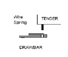
The standard drawbar used by most manufacturers and fitted to the rear of the locomotive has a wire spring soldered to it to provide side pressure onto the tender pin. This standard type drawbar does not always suit the tender pin diameter and I have found differences with various models – the pin does not always suit the drawbar hole.
The diameter of the drawbar hole compared to the diameter of the tender pin may be very close in tolerance that it inhibits the free movement of the tender and can prevent the tender from sitting freely on its frame and trucks.
If the tightness of the linkage of the drawbar and pin is too much it may hold the tender to one side or the other and prevent good electrical pick-up and tracking generally. In addition, if there is tightness between the drawbar and tender pin the tender may be “locked or held” into a position where it sits low or high preventing one or the other tender trucks to not be able to sit under ite own weight onto the track rails. This will inhibit good electrical contact something we are trying to achieve.
I have found that a free standing tender, once coupled to the locomotive, may have a “set” caused by the drawbar being too tight and holding the tender against its normal stance on the track.
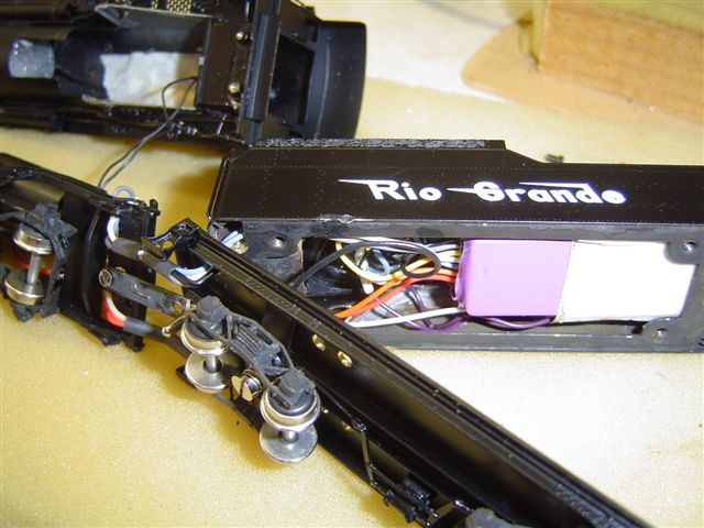
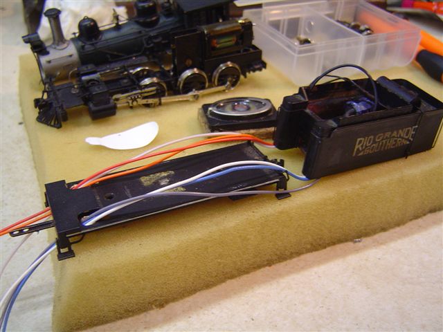
For the fitting of a DCC decoder the electrical connection is not required through the drawbar as the wire (Black) is soldered directly onto the tender frame. I am assuming the decoder and speaker are being fitted inside the tender.
To correct this problem on the drawbar I open the hole out half a millimetre larger so that the tender pin can rotate and rock freely yet still is firm enough to be held in place. I also move the wire spring to just be able to slightly “grab” onto the pin.
SOLDER CONNECTION ON TENDER:
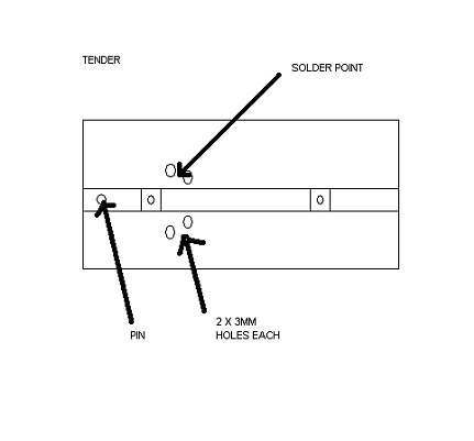
The next problem is getting a good solder connection on the tender frame for the BLACK Decoder wire.
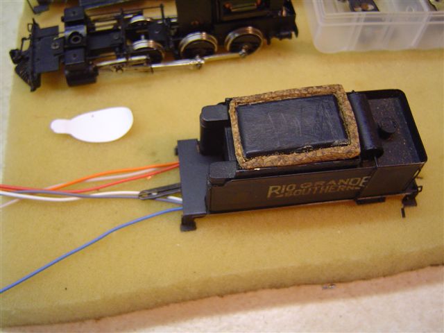
I do this by drilling 4 x 3mm holes through the brass floor plate which allows the sound an outlet from the speaker. Place 2 holes on either side of the centreline allowing 2mm between. The holes are in a close pattern directly above the front trucks rear set of wheels. The 2mm distance between the 3mm holes allows the “tinning” of the brass tender frame as it is only a small area to heat up and will take solder using a high temperature on my adjustable iron.
As a side note, I have found that 2 or 4, 3mm holes are more than enough to allow the sound out from the speaker and always fit an enclosure on the speaker.
ELECTRICAL PATH:
FROM RAIL THROUGH WHEELS / TRUCK / BODY.
The next problem is getting reliable electrical connection from the track through the wheels and brass trucks and onto the tender body frame. This electrical path is one whereby the rotating wheels have a tiny surface contact with the track and again a tiny surface contact with the axle to the truck frame and the truck frame has a rubbing contact with the tender frame. There are no true electrical joins in this path and the reliance is upon metal to metal contacts only!
All of this calls for cleanliness and good alignment. It is good to spray an electronic degreaser such as that available from Dick Smith’s or similar to the trucks and especially getting it into the bearing boxes where crud can build up at the axle ends. The use of a multimeter with an audible sound setting allows for positive checking of and electrical path. I use my meter for just this on my checks all over on brass locos and tenders and find it invaluable to problem solving shorts or checking electrical connections / continuity as in this case. Once the wheels are clean the next thing to check is the bolster. I use a wooden ice-cream stick with 400 grit wet-&-dry glued to it to polish the bolster and the truck mating surface to ensure that the surfaces are clean and flat. Remember this is part of the electrical path and must have a good contact. Check the wheel are in gauge by using the NMRA HOn3 gauge too!
The free movement of the truck is usually determined by the spring tension on the screw holding the truck to the frame. Too much tension and the truck will be stiff and derail especially on curves and turnouts. Too little and the electrical contact is made worse. Finding the happy medium is not that hard.
I cut the springs on each truck so that they have a LIGHT tension and I also add weight to the tender using lead to provide weight onto the wheels for better contacts. The springs need to fit loosely on the screws and must have the end of the wire turned over so it does not dig into the screw head or truck frame – this is very important to note.
The screws are designed to accommodate the springs and also fit through the centre hole of the truck without binding. To check that the screw doesn’t clamp onto the truck cross plate, lightly push the screw through the truck when assembling it and then check it will freely move and tilt a little. This movement is to allow the truck to maintain contact with the track even if there are some uneven sections.
The next thing is to recheck the trucks have just enough free movement to rock from side to side a tiny bit. If they are too stiff then electrical contact and operation will suffer. Of course don’t make them too loose or the tender will wobble.
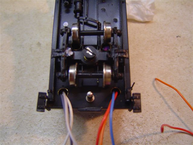
The next thing is to add extra pick-ups if the electrical contact supplies are erratic. This is done by super-gluing a small piece of printed circuit board to the inside of each truck frame and soldering a piece of phosphor-bronze wire to it so that it wipes in the axle or back of the pick-up side wheels. In addition to this, a tiny wire can be soldered from the PCB to the tender body to assist in creating a better electrical path.
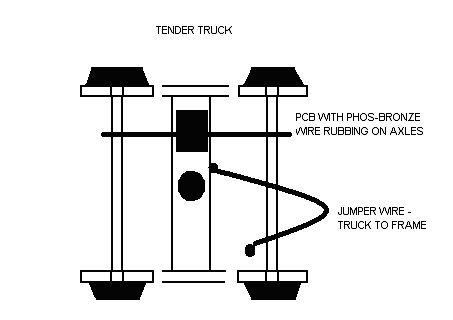
A further improvement is to solder a tiny wire from the brass truck to the frame allowing free movement – I use decoder wire and place a small “S-bend in the wire.
The figure shows the added Printed Circuit Board (PCB) with the phosphor-Bronze wire soldered to it and rubbing against the axle. A jumper wire has been added being soldered to the truck and tender body.
ADDING WEIGHT TO THE TENDER:
The addition of weight is sometimes needed to provide enough “downward pressure” to the tender upon the trucks to permit sufficient metal-to-metal contacts in the trucks.
It should be noted that this may inhibit the amount of rolling stock the locomotive can pull so go a bit at a time.
A good test is to get some lead fishing sinkers of different sizes/weights and place them on the tender and run the loco before fitting a decoder. I have a timber length with 2 pieces of flex-track on it for testing purposes and an old 12v supply via a transistor throttle. It is amazing the difference weight on the tender makes to the brass locomotive (and also the loco too!). If the pick-up improves with weight it may be that the axle to truck frame is a poor connection or that the truck to tender through bolster has a poor surface connection or both.
To remedy this you may swap a tender from a known locomotive you know onto the new loco and test them together – it is a process of elimination – finding the fault and learning more along the way.
Another way is to replace the tender wheels or trucks completely with good quality replacements.
I hope this helps you solve the electrical pick-up problem/s on your loco. Don’t forget to clean the wheels too.