NR Class – Decoder Installs
This is the second release of the NR class by Austrains and this time consideration has been given to installing a sound decoder and speaker as well as a good light selection.
This page will show you how to install a Tsunami AT1000 GE sound decoder and a reasonable speaker.
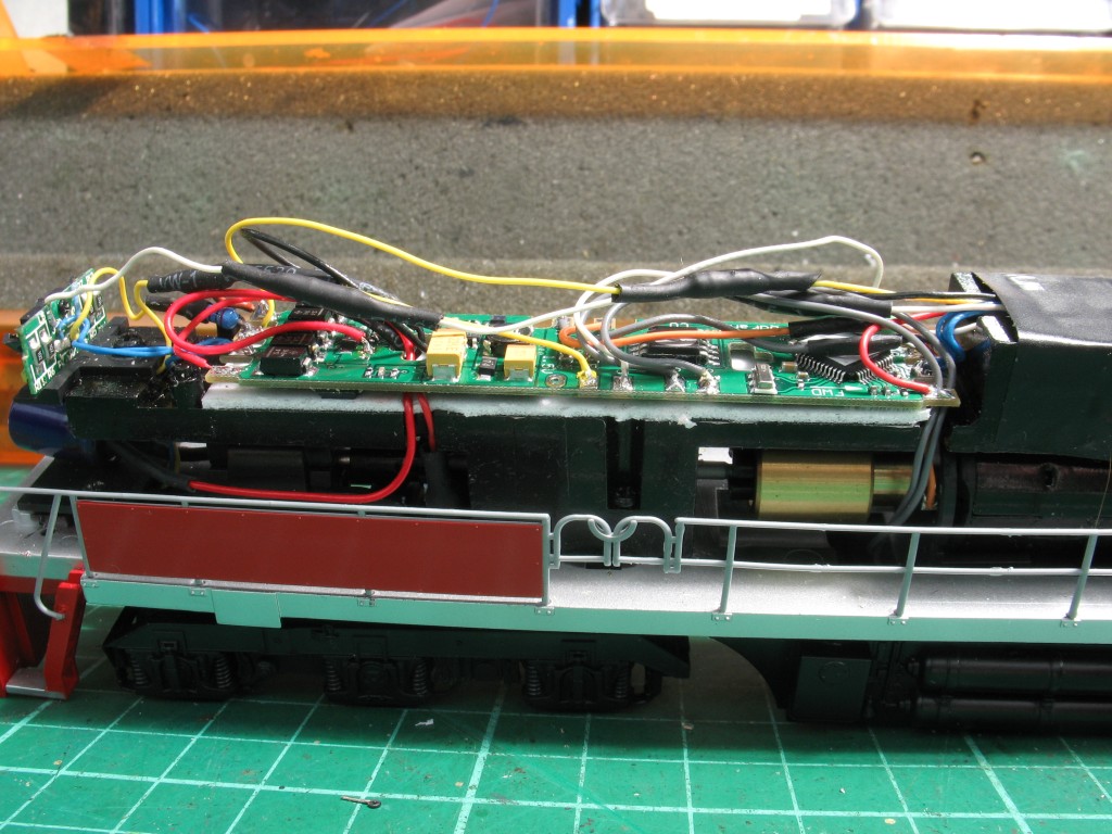
Run the wires from below the board up through the holes in the middle, there is no room for them to run around the board.
The black heat shrink tubing covers the 1k 1/4 watt resistors for the LEDs at the front and the rear.
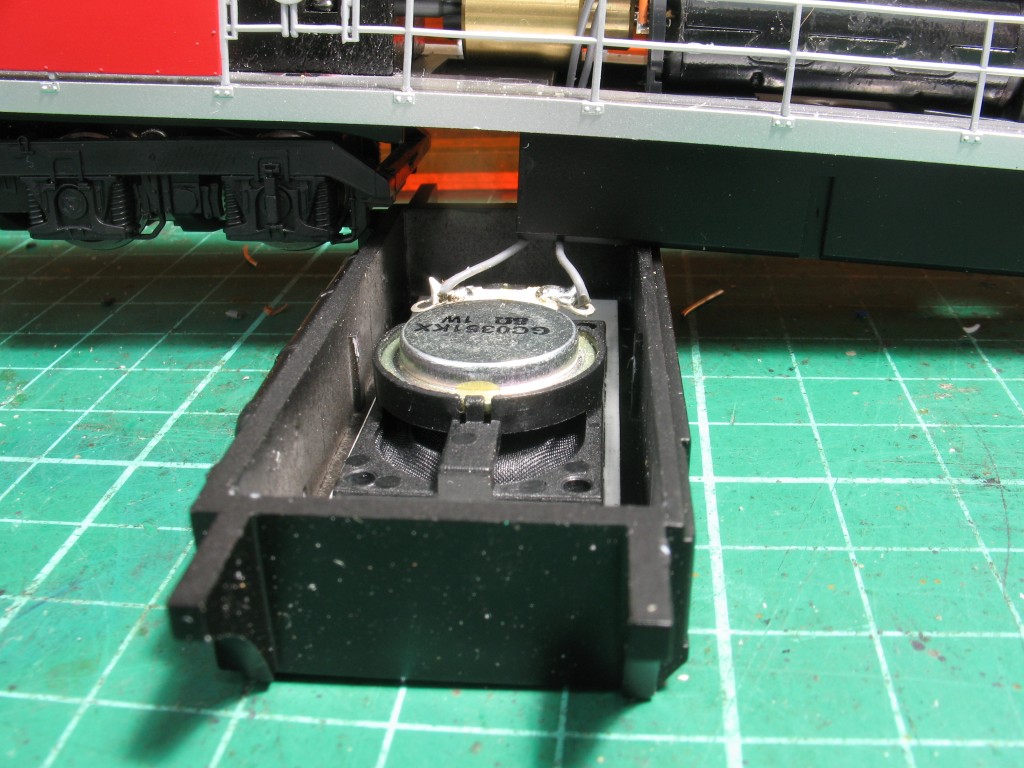
This makes it very quiet and not worth fitting a sound decoder. BUT, there is plenty of room in the fuel tank as shown here. Remove the two slide switches and their wires you will be able to control the lights from the decoder.
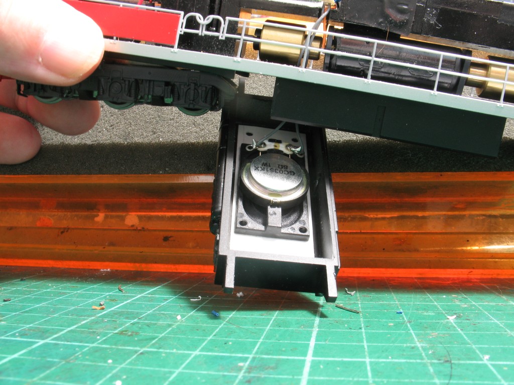
Drill some 3mm holes in the bottom of the tank to allow the sound “to get out”, then cover the bottom of the tank with something to keep the dirt out. I use a small piece of material cut from old pantyhose.
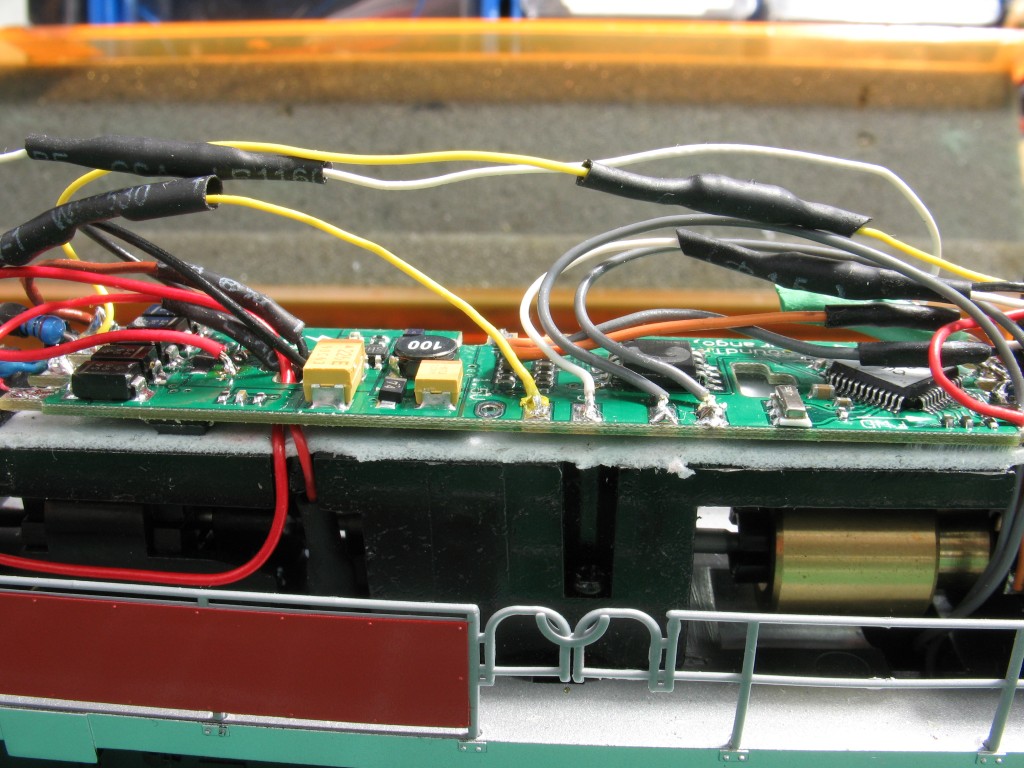
Join the two blues together and solder to the “common” connection on the front of the decoder. The white wire is connected to the “Headlight Connection” on the decoder through a 1k 1/4 watt resistor.
The wires from the light board at the rear of the loco are connected in a similar manner, the yellow to the rear of the board and the white to the front of the board. Remember to fit a resistor to each wire.
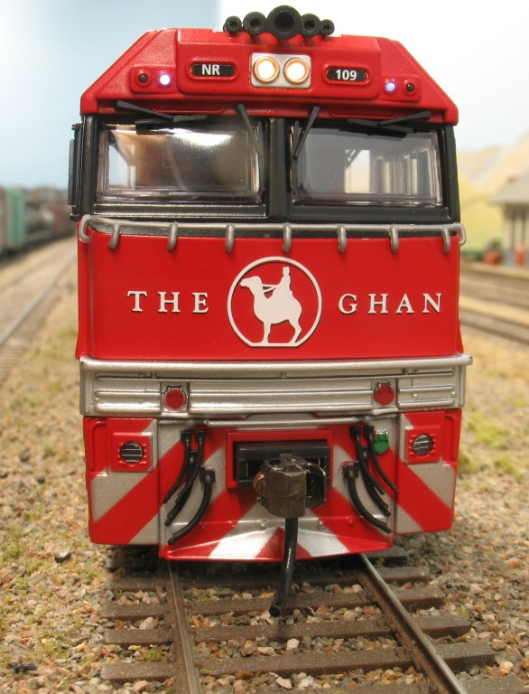
This photo shows the lower marker lights (Ditch Lights). The blue wire from the front is attached to the common with the other blue wires. The white wire from the front is attached to the pad marked “F6” on the decoder through a 1k 1/4 watt resistor.
The yellow wire from the rear ditch lights goes to the “F5” pad on the decoder.
The “F5” pad is remapped to “F1” and the “F6” pad is remapped to “F3”. This will allow individual control of the Ditch Lights.
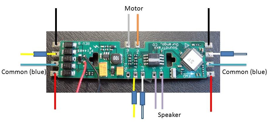
The RED wires go to the right hand rail and the BLACK wires go to the left hand rail.
CVs to be changed
Decoder Pro
Download and save NR Class your Decoder Pro Roster. In Decorder Pro, run “Recreate Roster” then you can use it to program your loco NR_109.xml
Download NR_109 pdf if you do not have Decoder Pro. It is a single page pdf – the CVs you need to change are highlighted in yellow.