by Gerry Hopkins MMR

Some views of the extra work undertaken for the sound install in a Brass O Scale Big Boy. The decoder is a TCS WOW v4 501 decoder.
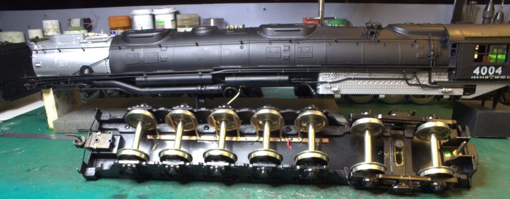
The underside of the tender – plenty of wheels – added pickups to the right hand side.
I used a length of pcb sleeper from Clover House and phosphor bronze for the wipers.
The pcb is screwed and glued to the chassis.
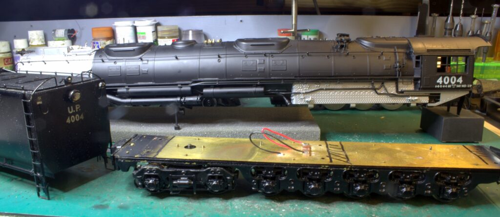
This is the top side of the tender chassis. the black marks indicate where the cross braising of the tender body sits.
The red and black wires are soldered to the pcb in the middle.
The red from the new pickups and the black is soldered to the chassis.
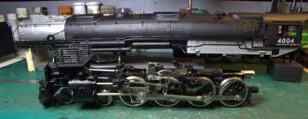
This is the lead engine – weighs a ton – The bulb in the headlight was replaced with a 0603 SMD LED.
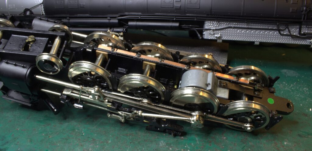
This is the underside of the lead engine.
The pcb has been screwed in place and is ready to have the wipers added.
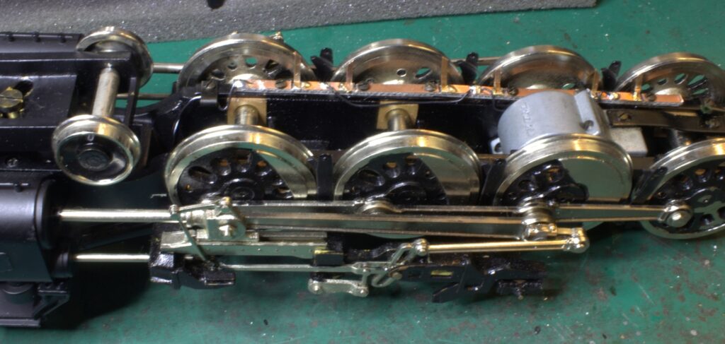
The wipers have now been added and the contact parts of the pcb have been linked.
The black/white wire to the left of the lead axle is the new lead from the headlight. It uses a pad at the front of the pcb just as a convenient connector.
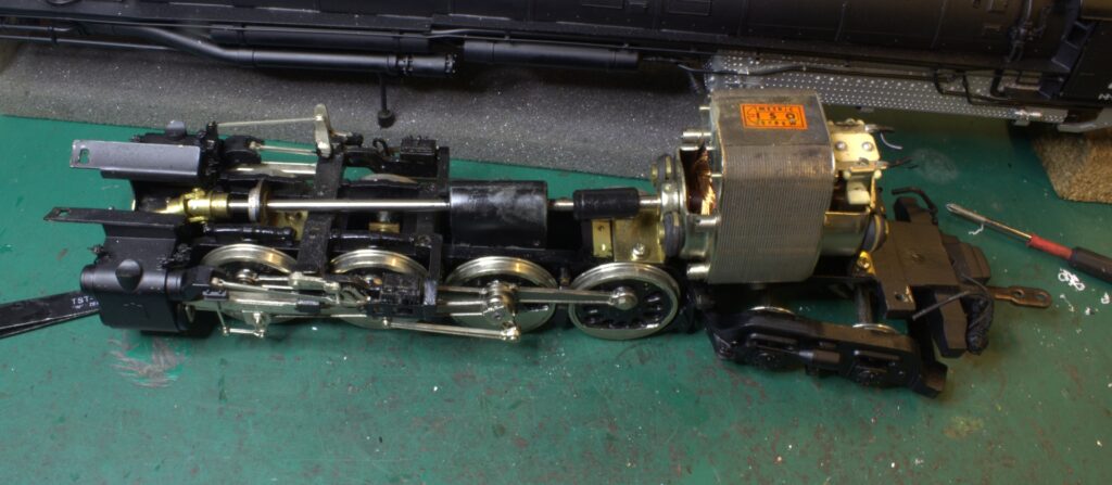
Rear engine removed from the body – look at the motor!
The motor will be replaced by a can motor – a Pittman Can #9414 – measures 60mm x 40mm
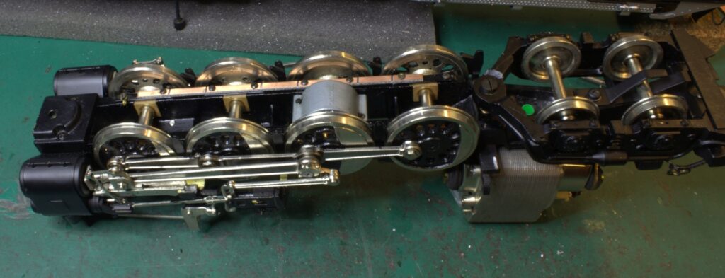
CB has been cut and is ready to take the wipers.
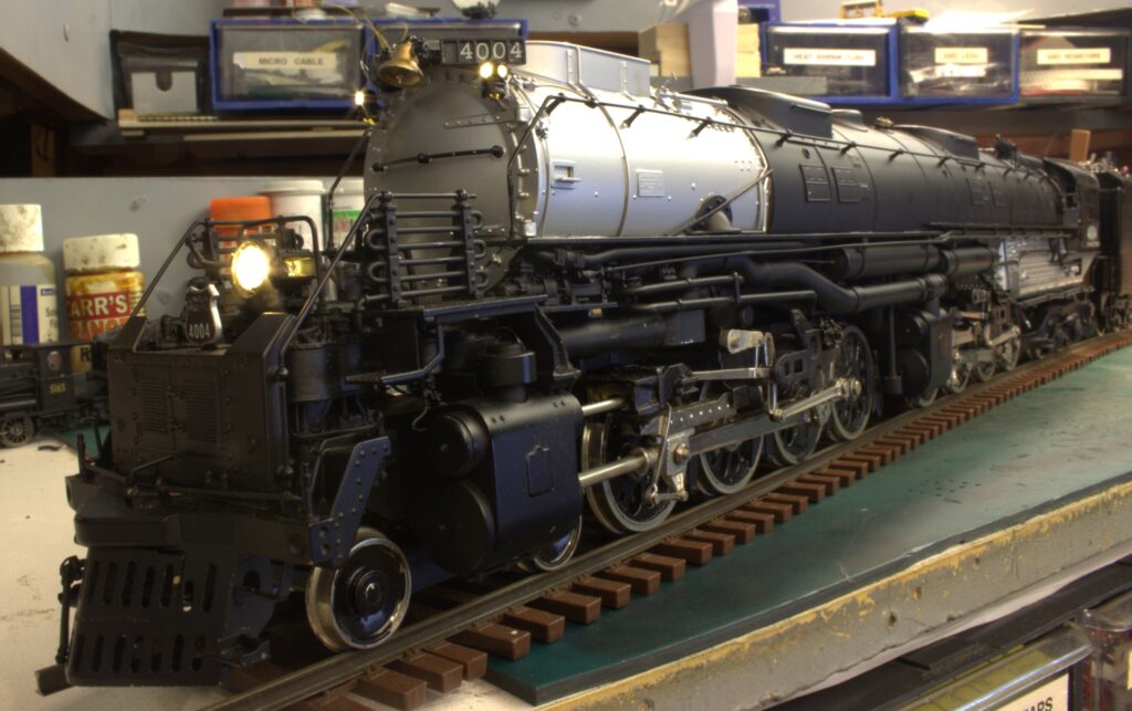
Front Markers on F9 using two 0603 SMD LEDs in series with 3k3 SMD resistor.
Headlight on F0f is a 0603 SMD LED in series with 1k0 SMD resistor.
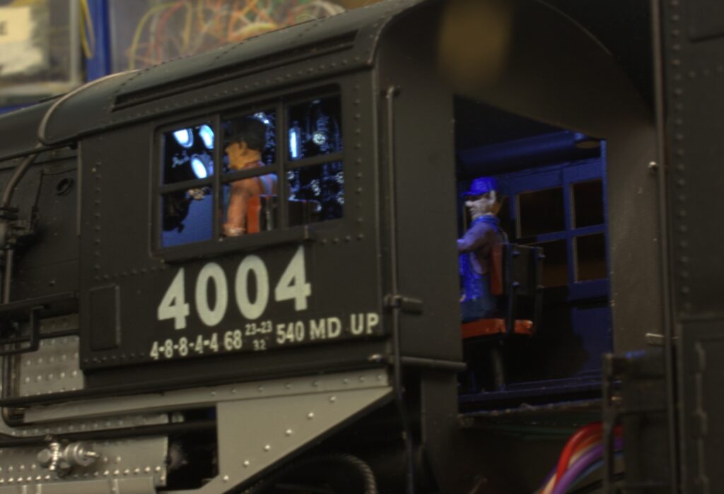
Cab interior light on F10 using a 0603 SMD LED and a 3k3 SMD resistor.
George is the fireman and Claude is the engineer.
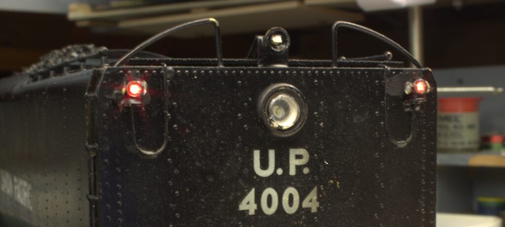
When going forward the two rear markers are red and can be turned on with F11.
They are fibre optics tgoing back to a bi-colour 3528 SMD LED.
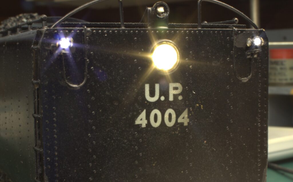
When in reverse the backup light on F0r and the white markers on F9.
The backup light is a 0603 SMD LED with 1k0 SMD resistor.
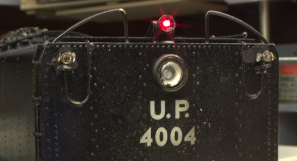
With the loco in reverse and just parked, the red strobe can be turned on with F5 – another 0603 SMD LED with 1k0 SMD LED resistor but this time red.
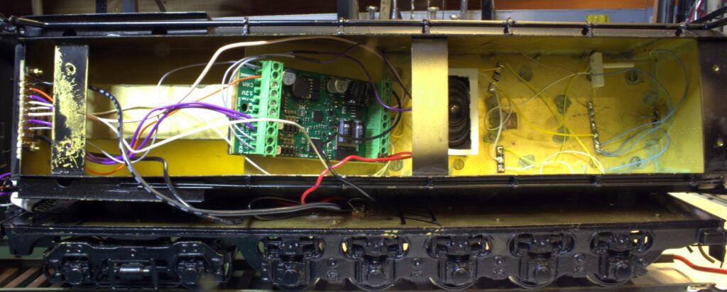
Inside the tender.
The wires will be tidied up.
The decoder is mounted on the underside of the coal bunker.

The socket is mounted at the front of the tender on a pc board.
Easy to get to and no danger of shorting against anything.
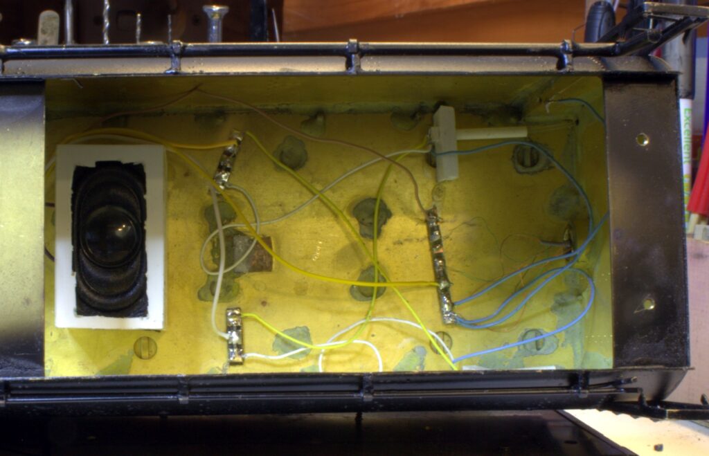
This shows the Auxilary speaker in the tender – the main speaker is in the smokebox and will blow your socks off!!
Also shown are the SMD resistors on connection boards for the rear lights.
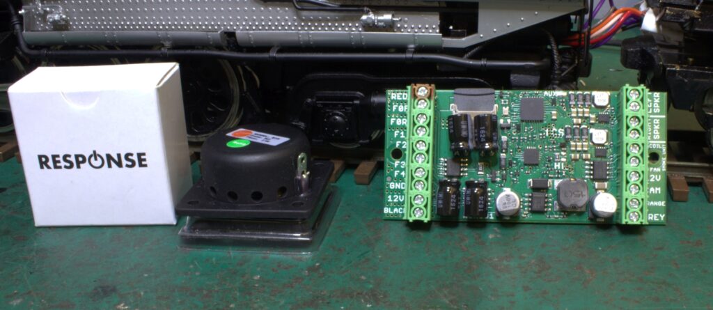
The main speaker – is a Jaycar 3030 and the WOW 501 Decoder from Train Control Systems.
All programming is done with a Sprog 3 using Decoder Pro.
Those who are very brave and have plenty of time can use Audio Assist for some of the programming.
