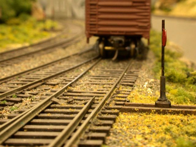
I switch all of the easily accessible turnouts on my Cedar Valley Short Lines with slide switches I have altered to my own design. They are robust, inexpensive, easy to construct, route power to the turnout frogs, look similar to prototype switch stands and have moveable targets which show which way the turnout is thrown. The first photo shows a finished turnout throw in place on the layout with the slide switch itself concealed, the switch stand attached to the toggle, the moveable target and the throw bar to the turnout.
I developed these modified slide switches after years of trying other methods. The usual electrical methods with their attendant wires, switches, indicator lamps or LEDs didn’t appeal because of all the complexity and under-layout wiring and maintenance that was required.
I tried the commercial throw-over throws but felt they spoilt the appearance of the layout, particularly in photographs. I tried slide switches mounted on brackets under the layout but they were difficult to install and adjust and if mounted too far from the turnout, could be unreliable.
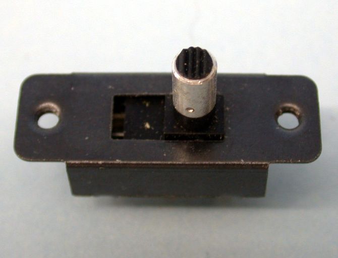
I came up with something simpler, better and that I could construct and install in 30 minutes or so. Instead of mounting the slide switches under the layout, I mount them right on the upper surface, adjacent to the turnout throw rod and recessed into the Canite (Homasote). To build one of these throws and its attached switch stand, start with a double pole, double throw slide switch with no centre off position and preferably a round toggle, not a rectangular one. If the latter, simply file the toggle round to make it represent a prototype switch stand base. The next photograph shows a switch as bought from Dick Smith’s for approximately 90 cents.
The first job is to simply twist the aluminium sleeve off with pliers, then cut the toggle down to a scale 2 feet (in HO) above the expected ground level. Round the top edge with a file and if the toggle is not already black, paint it black now.
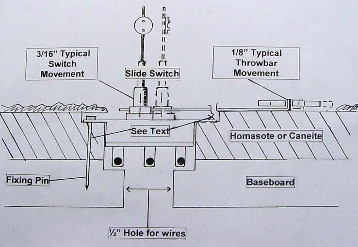
Then carefully drill a 0.031-inch hole for the actuating rod through the base of the lowered toggle, making sure it is both parallel to the top and sides of the switch. Cut a piece of 0.031 inch brass wire about 4 inches long, turn up one end about ¼ inch and insert through the hole in the base, making sure there are no burrs and the rod is a firm sliding fit with enough resistance to throw the turnout. Commercial turnouts throw around 1/8 inch or so and slide switches only 3/16 inch approximately. The firm, sliding fit takes care of this difference.
Then drill another 0.031-inch hole but this time vertically into the lowered toggle which will allow the about-to-be-installed switch stand staff to swivel. For high stands (main line) make the staff from a piece of the 0.031 inch brass rod approximately 8 scale feet high. For low stands (sidings and yards) make the staff 3 scale feet high. Solder a 1/8 inch diameter washer approximately 2 scale feet from the top, fill with solder, file smooth, paint the staff black and the target red. Drop the targeted staff into the toggle and make sure it swivels freely.
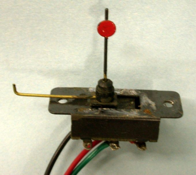
Solder on the electrical wires, one side to power the frog and the other, if desired, to operate a lineside signal or remote panel lamp. The next picture shows the completed unit ready for installation on the layout.
Using your NMRA clearance gauge, mark a rectangular area adjacent to your turnout throw bar the exact size of the base of the slide switch with the tab of the slide switch to fit just under the turnout ties to secure that end.
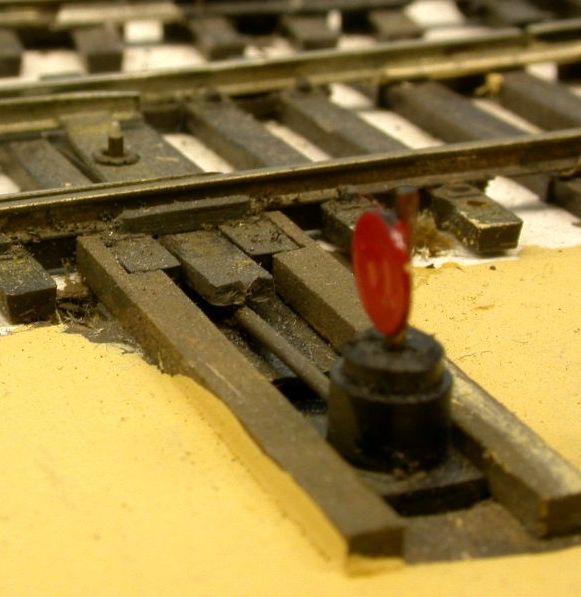
Carefully excavate the Canite (Homasote) making sure that the slide switch is held securely by the Canite when in the hole, drill a 1/4 inch hole through the ply sub-base for the electrical wires, insert the bent-up end of the actuating rod through the hole in the centre of the turnout throwbar, drop the slide switch into the hole, carefully feeding the wires through the ply, secure the points in the centre position with masking tape and centre the slide switch toggle in the switch, also with tape.
To secure the other end of the slide switch, drill a small hole through the hole in the tab into the Canite enough to also penetrate the sub-roadbed somewhat and drive a long panel pin through the Canite into the sub-base. Note that this fixing may not be necessary if the hole is correctly sized and the area is sceniced. Remove the tape and operate the switch by grasping the lower part of the toggle between finger and thumb, moving it as you would any slide switch, (Yes, the whole turnout and target moves but that will not be noticed in operation). If satisfied that all works well, cut off the surplus brass actuating rod, install a scenicing mask made out of 0.010 inch styrene, install dummy adjoining ties, touch up the paint and apply your choice of ground cover.
I have used this system for over 15 years and it works well. I have installed approximately 80 on the current layout and our walk-around operators like them too as they can see exactly what is happening as they throw the switches as well as also being guided by distant targets.
Note: My article on this method was published in the January/February 1994 issue of the NG&SL Gazette. Following extensive experience, the method above is an easier and simpler approach.